A few months back, I was consulting with a propulsion systems team at a mid-sized aerospace contractor who had just scrapped an entire batch of turbine brackets — roughly $200K worth of titanium alloy parts — because they’d switched AM vendors without re-qualifying the process parameters. The parts looked perfect on the outside. Internally? Swiss cheese porosity. That war story stuck with me, and it kicked off a pretty deep dive into why not all additive manufacturing processes are created equal when it comes to aerospace applications.
If you’re in aerospace engineering, procurement, or even just researching how AM is reshaping the supply chain in 2026, buckle up. We’re going to compare the major additive manufacturing (AM) processes used for aerospace parts — not just theoretically, but from the “what actually happens on the shop floor” perspective.
Why Aerospace AM is a Different Beast Entirely
First, let’s set the stage. Aerospace isn’t like printing consumer goods or even automotive prototypes. Every process decision feeds into FAA certification (or EASA, JCAB, depending on region), material traceability, and ultimately flight safety. In 2026, the AM certification landscape has matured significantly — the FAA’s AC 21-303 additive manufacturing guidance and AMS7000/7003 specifications from SAE International now provide clearer frameworks — but the qualification burden is still very real.
So when we compare processes, we’re not just comparing “print quality” — we’re comparing material density, anisotropy behavior, thermal residual stress, post-processing burden, and cost-per-qualified-part. Let’s get into it.
Powder Bed Fusion (PBF): The Aerospace Workhorse
Powder Bed Fusion splits into two dominant camps for aerospace: Laser Powder Bed Fusion (L-PBF) and Electron Beam Powder Bed Fusion (EB-PBF). Both sinter/melt metal powder layer by layer, but their operating environments differ dramatically.
- L-PBF (e.g., EOS M 400-4, Trumpf TruPrint 5000, SLM Solutions NXG XII 600): Works in inert argon atmosphere, layer resolution of 20–80 µm, surface finish Ra ~4–12 µm before post-processing. Excellent for IN718, Ti-6Al-4V, AlSi10Mg parts. Residual stress is the enemy here — you WILL need stress relief HIP (Hot Isostatic Pressing) for flight-critical parts.
- EB-PBF (e.g., Arcam EBM Q20plus by GE Additive): Operates in high vacuum at elevated temperatures (~700–1000°C preheat for Ti alloys), which dramatically reduces residual stress. Parts come out nearly stress-free but with rougher surfaces (Ra ~25–35 µm). Great for Ti-6Al-4V hip implants AND aerospace brackets because of lower post-processing distortion.
- Density achievable: Both can hit >99.9% relative density when process parameters are dialed in. But “dialed in” is the operative phrase — the bracket batch I mentioned earlier was an L-PBF re-run with laser power settings copied from a different alloy. Never do that.
- Build volume constraint: Most L-PBF machines top out around 500×280×365 mm. For large structural aerospace parts, this is a hard limit.
Directed Energy Deposition (DED): Big Parts, Big Trade-offs
When you need to print something the size of a wing spar segment or repair a turbine blade tip, DED is where you turn. Technologies here include Laser Metal Deposition (LMD) and Wire Arc Additive Manufacturing (WAAM).
- WAAM (used by companies like NORSK Titanium, Cranfield Waam3D) deposits metal wire via electric arc at deposition rates of 1–10 kg/hr — orders of magnitude faster than powder bed. In 2026, Norsk’s RPD® (Rapid Plasma Deposition) process is certified for structural Ti-6Al-4V Boeing 787 components, which is a massive validation milestone.
- LMD (machines from Optomec, BeAM, DMG Mori LASERTEC) uses powder feed nozzles with 5-axis capability — great for repair of turbine blades and adding features to existing parts (hybrid manufacturing).
- Surface finish: DED is rough. Ra values of 50–200 µm are common. Machining allowances of 1–3 mm are typically built into the design. This is not a net-shape process for most aerospace applications.
- Material microstructure: The fast thermal cycling in WAAM creates columnar grain structures that cause anisotropic mechanical properties (stronger in one axis than another). Post-process HIP + heat treatment can partially equiaxe the grains, but this adds cost and schedule.
Binder Jetting: The Dark Horse for High-Volume Production
In 2026, Binder Jetting (BJT) has matured considerably for aerospace metallic applications. ExOne (now Desktop Metal), HP Metal Jet S100, and Markforged Metal X platforms are printing stainless steel, Inconel, and even some Ti alloys by binding powder then sintering in a furnace.
The key aerospace attractiveness: no support structures needed for most geometries, high throughput, and lower machine cost per part at volume. The concern? Sintering shrinkage is 15–20% and somewhat non-uniform, making tight-tolerance aerospace parts very challenging. Dimensional accuracy after sinter is typically ±0.3–0.5 mm — acceptable for brackets and clips, but not turbine seals.
Composite AM: Continuous Fiber for Non-Metallic Structures
Not everything in aerospace is metal. Continuous Fiber Fabrication (CFF) by Markforged and Automated Fiber Placement (AFP)-inspired AM systems are producing CFRP and glass-fiber reinforced thermoplastic parts. PEEK + continuous carbon fiber brackets are flying on satellite structures and UAVs today. Specific strength rivals aluminum while cutting mass by 30–40%.
Stratasys’s F900 ULTEM 9085 FDM system — while technically FFF (Fused Filament Fabrication) — remains the industry standard for interior cabin parts (FAR 25.853 flame-retardant compliance), with thousands of flying certifications from Airbus and Boeing supply chains.
Head-to-Head Process Comparison: The Numbers That Matter
- L-PBF: Resolution ★★★★★ | Surface Finish ★★★★☆ | Part Size ★★☆☆☆ | Speed ★★☆☆☆ | Material Density ★★★★★
- EB-PBF: Resolution ★★★☆☆ | Surface Finish ★★☆☆☆ | Part Size ★★★☆☆ | Speed ★★★☆☆ | Residual Stress ★★★★★
- WAAM: Resolution ★★☆☆☆ | Surface Finish ★☆☆☆☆ | Part Size ★★★★★ | Speed ★★★★★ | Buy-to-Fly Ratio ★★★★★
- Binder Jetting: Resolution ★★★★☆ | Surface Finish ★★★☆☆ | Part Size ★★★☆☆ | Speed ★★★★☆ | Dimensional Accuracy ★★★☆☆
- CFF/FFF Composite: Resolution ★★★☆☆ | Structural Strength ★★★★☆ | Weight Savings ★★★★★ | Certifiability ★★★☆☆ | Cost ★★★★★
Real-World Case Studies: Who’s Actually Using What in 2026
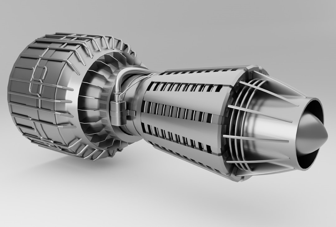
GE Aerospace’s CFM LEAP Engine Fuel Nozzle remains the canonical L-PBF success story — 19 parts consolidated into 1, 25% weight reduction, 5x durability improvement. By 2026, GE has printed over 100,000 of these nozzles. Their internal qualification data (published through ASTM International’s AM standards working group) shows consistent mechanical properties when L-PBF parameters are locked and powder lots are certified.
Airbus’s Bionic Partition (A320 cabin divider) used Scalmalloy® aluminum alloy on EOS systems — topology-optimized, 45% lighter than conventional, and now progressing toward structural use cases in A350 programs according to their 2026 Digital Continuity roadmap.
Relativity Space and Rocket Lab push AM to the extreme — Relativity’s Terran R uses WAAM-derived processes for their Aeon engines, printing the entire engine structure. Rocket Lab’s Rutherford engine uses L-PBF for the combustion chamber and injector. Both represent “AM-first” design philosophy rather than “replace conventional” thinking.
For composite AM, Boom Supersonic’s XB-1 demonstrator program used AFP and composite AM tooling extensively, with several interior bracket applications in PEEK that reduced their supply chain lead time from 14 weeks to 11 days. That’s not a typo.
The Post-Processing Reality Nobody Talks About
Here’s the engineering truth that often gets buried in vendor marketing: the AM machine is roughly 30–40% of the total production cost for most flight-critical aerospace parts. The rest? Post-processing.
- HIP (Hot Isostatic Pressing): Mandatory for most flight-critical L-PBF and EB-PBF parts. Closes residual porosity, homogenizes microstructure. Cost: $50–500 per part depending on batch size. Cycle time: 4–8 hours + furnace scheduling delays (often weeks at external vendors).
- Heat Treatment: Solution anneal + age for IN718; STA (Solution Treated and Aged) for Ti-6Al-4V. Required to hit AMS spec mechanical properties.
- CNC Finish Machining: Critical surfaces (bearing interfaces, seal grooves, bolt holes) always need machining regardless of AM process. Budget 1–3 machining ops minimum.
- NDT (Non-Destructive Testing): CT scanning for internal defect detection is now considered standard practice, not optional. A good CT scan on a medium-sized L-PBF part runs $300–800 and takes 2–4 hours of analysis time.
- Surface Treatment: Anodizing, PVD coating, shot peening for fatigue improvement — all standard aerospace finishing that doesn’t go away just because you changed the manufacturing method.
Choosing the Right Process: A Decision Framework
So how do you actually choose? Here’s the engineering decision tree I use when helping aerospace teams select an AM process:
- Part volume > 500mm in any dimension? → Start with DED/WAAM. L-PBF build envelope likely won’t accommodate it.
- Part is non-metallic structural or interior? → FFF/CFF with ULTEM or PEEK. Established certification paths exist.
- High complexity, many internal channels, < 300mm? → L-PBF is your friend. Design freedom is unmatched.
- Ti-6Al-4V structural, residual stress is critical concern? → EB-PBF deserves serious evaluation despite rougher surface finish.
- Medium complexity, need high volume > 1000 parts/year? → Binder Jetting economics start winning. Invest in fixture and sintering profile development.
- Repair or add-on features to existing parts? → LMD/DED hybrid machining centers (DMG Mori, Mazak Integrex AM) are the go-to solution.
Where the Industry Is Heading in 2026 and Beyond
The most exciting development in aerospace AM right now isn’t a new machine — it’s in-situ process monitoring and closed-loop control. Companies like Sigma Additive Solutions (now part of Divergent Technologies), Velo3D, and Concept Laser (GE) are integrating melt pool monitoring, layer-by-layer optical tomography, and AI-driven parameter adjustment to catch defects in real time rather than discovering them during post-process CT inspection.
Velo3D’s Sapphire XC 1MZ with Flow software uses real-time melt pool data to self-correct during the build — reducing the reliance on exhaustive post-process NDT and potentially accelerating the qualification cycle significantly. In 2026, this technology is approaching production-readiness for select alloy-geometry combinations.
Another trend: multi-material AM. NASA’s Marshall Space Flight Center has demonstrated bimetallic structures with copper-alloy cooling channels embedded in steel rocket nozzle bodies using DED — something impossible with conventional machining.
Conclusion: There’s No Single Winner, But There IS a Right Answer for Your Case
The mistake that cost that aerospace team $200K wasn’t choosing the wrong AM process — it was treating all AM processes (and even all vendors running the same process) as interchangeable. In aerospace, process IS the product. A Ti-6Al-4V part printed at 195W laser power with 30µm layers and a specific scan strategy has fundamentally different mechanical properties than the “same” part printed at a different power-speed combination.
The good news: in 2026, the standards infrastructure (AMS7000 series, ISO/ASTM 52900 family, NASA-STD-6030), the process monitoring technology, and the accumulated industry knowledge have matured to the point where AM is no longer a moonshot for aerospace production. It’s an engineering discipline — demanding, nuanced, but absolutely learnable.
Start with clearly defined requirements, work backward to process capability, and never — ever — change a qualified parameter without re-qualifying. Your future self, and the people flying on those parts, will thank you.
Editor’s Comment : If you’re just starting your aerospace AM journey, I’d strongly recommend downloading the publicly available NASA-STD-6030 Additive Manufacturing Requirements for Spaceflight Systems (free on the NASA Technical Standards System) and cross-referencing it with SAE AMS7003. These two documents together will give you a realistic picture of what qualification actually looks like — and trust me, it’s better to understand that early than to discover it mid-program when schedule pressure is at its worst.
📚 관련된 다른 글도 읽어 보세요
- Bio 3D Printing Artificial Organs in 2026: The Latest Research That Could Redefine Human Health
- Home Lab Network VLAN Setup Guide 2026: Segment Your Network Like a Pro (Without Losing Your Mind)
- 3D 프린팅 자동차 부품 양산, 2026년 지금은 현실이 될 수 있을까?
태그: []
Leave a Reply