지난달에 친한 후배가 카톡을 보내왔어. ‘형, 전기차 지금 사도 될까요? 보조금이 줄었다는데…’ 솔직히 나도 한참 고민했던 주제라 바로 답장 못 하고 며칠 동안 직접 발품 팔아서 데이터를 모았어. 딜러 3곳 방문하고, 실소유자 커뮤니티 뒤지고, 환경부 보조금 시스템 직접 돌려보고 나서야 답을 줄 수 있었거든. 결론부터 말하면 — ‘무조건 사라’도 아니고, ‘절대 사지 마라’도 아냐. 조건이 맞는 사람한테는 여전히 매력적이고, 조건이 안 맞는 사람한테는 진짜 돈 버리는 짓이 될 수 있어. 이 글에서 그 조건을 낱낱이 파헤쳐볼게.
- 📌 2026년 전기차 보조금, 얼마나 줄었나? 실수령액 계산법
- 📌 전기차 vs 하이브리드 vs 내연기관 — 5년 총소유비용 비교
- 📌 국산 vs 수입 전기차, 지금 시장에서 실제로 살 만한 모델은?
- 📌 절대 하지 말아야 할 전기차 구매 실수 5가지
- 📌 이런 사람은 사도 되고, 이런 사람은 1년 기다려라
- 📌 자주 묻는 질문 (FAQ)
📌 2026년 전기차 보조금, 얼마나 줄었나?
환경부 무공해차 통합누리집 기준으로 2026년 전기차 국고 보조금은 차종과 성능에 따라 차등 지급돼. 핵심만 정리하면 이래:
- 국고 보조금: 승용 기준 최대 580만 원 (2023년 680만 원 대비 약 15% 축소)
- 지자체 보조금: 서울 180만 원, 경기 250만 원, 지방 소도시 최대 500만 원까지 차이 극심
- 총 보조금 실수령 최대: 수도권 기준 약 700~800만 원, 지방 기준 최대 1,000만 원 이상 가능
단, 보조금은 차량 가격에 따라 100% → 50% → 0%로 구간이 나뉘어. 5,500만 원 미만이면 100% 수령 가능, 5,500~8,500만 원은 50%, 8,500만 원 초과는 보조금 없음. 제네시스 GV80e, BMW iX 같은 고급 전기차 노리는 분들은 처음부터 보조금 기대 접어야 해.
📌 전기차 vs 하이브리드 vs 내연기관 — 5년 총소유비용 비교
감가상각, 연료비, 유지비, 보험료, 세금 다 때려넣고 계산했어. 연간 주행거리 2만 km, 서울 거주, 5년 보유 기준이야.
| 항목 | 전기차 (아이오닉6 롱레인지) | 하이브리드 (아반떼 HEV) | 내연기관 (아반떼 1.6) |
|---|---|---|---|
| 구매가격 (보조금 후) | 약 3,900만 원 | 약 2,700만 원 | 약 2,100만 원 |
| 5년 연료비 (2만km/년) | 약 250만 원 (전기요금) | 약 700만 원 | 약 1,100만 원 |
| 5년 유지보수비 | 약 150만 원 | 약 350만 원 | 약 550만 원 |
| 5년 감가상각 | 약 1,600만 원 (41%) | 약 900만 원 (33%) | 약 650만 원 (31%) |
| 5년 총소유비용 | 약 6,000만 원 | 약 4,800만 원 | 약 4,500만 원 |
⚠️ 숫자가 전기차한테 불리하게 나왔지? 핵심은 감가상각이야. 배터리 기술이 빠르게 발전하면서 현재 전기차 모델의 중고차 가격 하락폭이 여전히 커. 반면 5년 이상 장기 보유하거나, 연간 주행거리가 4만 km를 넘어가면 연료비 절감 효과로 역전이 가능해. 많이 타는 사람일수록 전기차가 유리한 구조야.
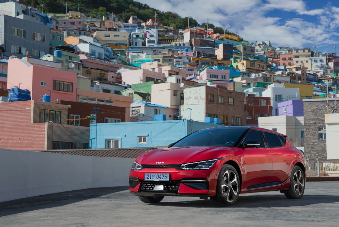
📌 국산 vs 수입 전기차 — 지금 살 만한 모델 실전 비교
2026년 기준 실제 출고 가능하고, 보조금 적용 후 현실적인 선택지만 추렸어.
| 모델 | 실구매가 (보조금 후) | 1회 충전 주행거리 | 급속충전 속도 | 추천 대상 |
|---|---|---|---|---|
| 아이오닉6 롱레인지 RWD | 약 3,800~4,000만 원 | 614km (공인) | 800V / 18분 (10→80%) | 장거리 출퇴근족, 가성비 중시 |
| 기아 EV6 GT-Line | 약 4,000~4,300만 원 | 509km (공인) | 800V / 18분 | 디자인+성능 균형 중시 |
| 테슬라 모델3 RWD | 약 4,400~4,700만 원 | 578km (공인) | 250kW 슈퍼차저 | 충전 인프라 우선, OTA 선호 |
| BYD 씰 스탠다드 | 약 3,500~3,800만 원 | 570km (공인) | 150kW | 초기비용 최소화, 가격 민감층 |
| 폭스바겐 ID.4 Pro | 약 4,500~4,800만 원 | 521km (공인) | 135kW | 유럽차 감성, AS 안정성 중시 |
BYD가 국내 보조금 적용 대상에 포함되면서 가격 경쟁이 한층 치열해졌어. 다만 BYD는 국내 AS 네트워크가 아직 얇다는 게 실제 오너들의 공통 불만이야. 가격만 보고 덥석 계약하지 말고, 내 거주지 근처 공식 서비스센터 위치부터 확인해.
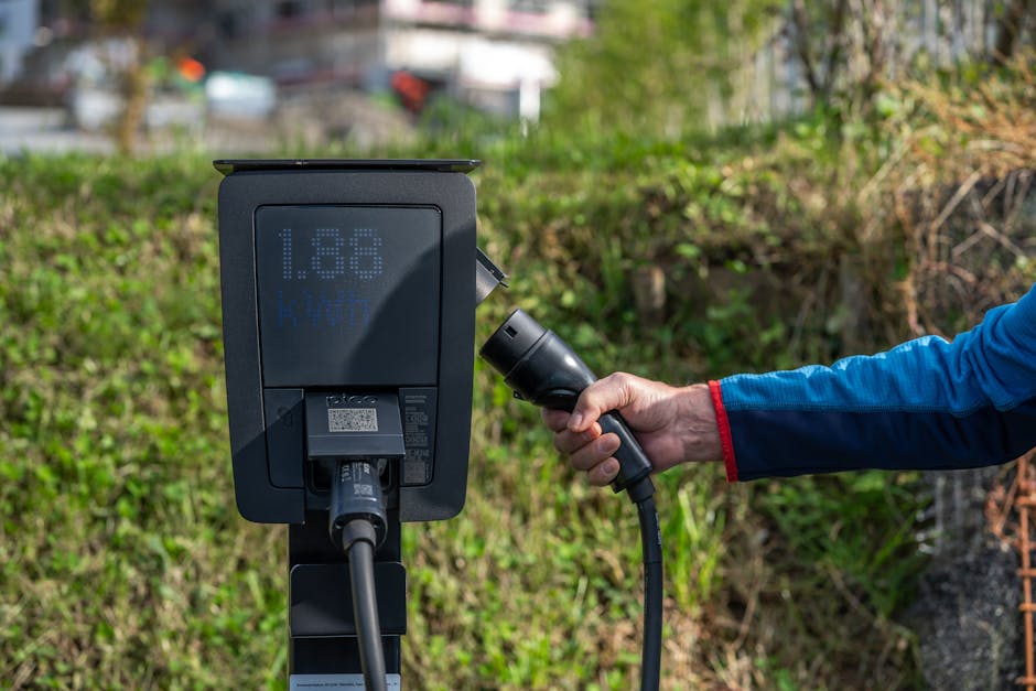
📌 국내외 충전 인프라 현황 — 실제로 불편하지 않나?
한국전력 및 환경부 충전 인프라 통계 기준, 2026년 1분기 현재 국내 급속충전기 설치 수는 약 35,000기를 넘어섰어. 수도권과 고속도로 구간은 체감상 크게 불편하지 않아. 문제는 지방 국도, 구도심 아파트 완속충전 대기 문제야.
- 고속도로 휴게소: 평균 6~10기 급속충전기 보급, 명절 제외 대기시간 15분 이내
- 도심 공용주차장: 충전기 고장률 평균 12% (한국소비자원 2025년 조사 기준)
- 아파트 완속충전: 입주민 갈등, 대기 없이 충전 가능한 세대 비율 아직 30% 미만
자가 충전 환경이 없는 분(아파트 충전기 없음, 노상 주차)은 진지하게 다시 생각해봐야 해. 아무리 전기요금이 싸도 외부 급속충전만 사용하면 연료비 절감 효과가 절반 이하로 떨어져.
🚫 절대 하지 말아야 할 전기차 구매 실수 5가지
- ❌ 실수 1: 공인 주행거리만 믿기 — 겨울 히터 켜면 공인 대비 30~40% 감소. 아이오닉6 614km 공인이어도 영하 10도에서 히터 풀가동하면 380km 안팎이야.
- ❌ 실수 2: 지자체 보조금 확인 안 하고 계약 — 거주지 변경 없이 보조금 수령 후 타 지역 이전은 환수 대상. 계약 전 반드시 해당 지자체 잔여 물량 확인.
- ❌ 실수 3: 자가 충전 환경 미확보 상태에서 계약 — 월 충전비용이 내연기관 대비 역전되는 상황 발생 가능.
- ❌ 실수 4: 배터리 보증 조건 미확인 — 제조사별로 ‘70% 용량 유지’ 또는 ‘배터리 교체 보증’ 조건이 달라. 특히 중국산 배터리 탑재 모델은 약관 꼼꼼히 읽어야 해.
- ❌ 실수 5: 보조금 마감 임박 심리에 끌려가기 — 딜러가 ‘이번 달 마감’이라고 압박해도, 보조금은 분기별로 재공고되는 경우 많아. 서두르다 원하지 않는 색상·옵션 계약하는 사람 정말 많아.
✅ 이런 사람은 지금 사도 되고, 이런 사람은 1년 기다려라
| 조건 | 판단 | 이유 |
|---|---|---|
| 연간 주행 3만km 이상, 자가 충전 가능 | ✅ 지금 사도 OK | 연료비 절감으로 5년 내 손익 분기 가능 |
| 지방 거주, 보조금 1,000만 원 이상 기대 가능 | ✅ 지금 사도 OK | 총소유비용 기준 하이브리드와 역전 |
| 아파트 충전기 없음, 연간 주행 1만km 이하 | ❌ 1년 기다려라 | 충전 불편 + 절감 효과 미미, 하이브리드가 합리적 |
| 3년 이내 차량 교체 계획 | ❌ 신중하게 | 감가상각 손실 크고, 배터리 기술 발전으로 중고값 더 하락 가능 |
| 신차 후 5년 이상 장기 보유 계획 | ✅ 긍정적 | 유지비 절감 + 배터리 성능 개선 모델 출시 전까지 충분히 뽑음 |
❓ FAQ — 독자들이 가장 많이 묻는 것들
Q1. 전기차 배터리 교체 비용이 진짜 2,000만 원이에요?
과거 초기 모델 이야기야. 현재 아이오닉5/6, EV6 기준 순정 배터리 교체 공식 견적은 1,200~1,500만 원 수준이고, 제조사 보증기간(10년 또는 20만 km) 내 용량 70% 미달 시 무상 교체 가능해. 단, 사고로 인한 배터리 손상은 보증 적용 안 돼 — 이건 차보험에서 커버되는지 가입 전 꼭 확인해야 해.
Q2. 겨울철 난방 때문에 주행거리가 너무 줄어드는 거 아닌가요?
솔직히 말하면 맞아. 영하 10도 이하에서 공인 대비 35~40% 감소는 현실이야. 대응책은 두 가지야. 첫째, 출발 전 실내 주차 상태에서 ‘예열 모드’를 활용해 배터리 온도를 올려두는 것. 둘째, 히트펌프 탑재 모델을 선택하는 것 — 히트펌프 없는 저항 히터 방식 모델은 전력 소모가 3배 이상 차이 나.
Q3. 테슬라 말고 국산 전기차 AS는 믿을 만한가요?
현대·기아 공식 서비스센터 네트워크는 국내 최대 수준이라 AS 접근성은 오히려 테슬라보다 나아. 다만 전기차 전담 정비 인력 숙련도는 지역별 편차가 있어. 차를 맡기기 전에 해당 서비스센터에 ‘전기차 전담 테크니션 있냐’고 직접 물어보는 게 좋아. 부끄러운 질문이 아니야 — 오히려 이걸 물어보지 않는 게 손해야.
한 줄 평: 전기차는 2026년 현재 ‘대세’가 맞지만, ‘나한테 맞는 대세’인지는 별개의 문제야. 충전 환경, 주행거리, 보유 기간 이 세 가지만 솔직하게 점검해도 답은 바로 나와. 보조금 줄었다고 겁먹을 필요도 없고, 딜러 말에 떠밀려 계약할 필요도 없어.
결국 전기차는 ‘기술’이 아니라 ‘라이프스타일’의 선택이야 — 내 생활 패턴이 전기차와 맞는지 먼저 따져보고, 그다음에 모델 고르는 순서로 가자.
📚 관련된 다른 글도 읽어 보세요
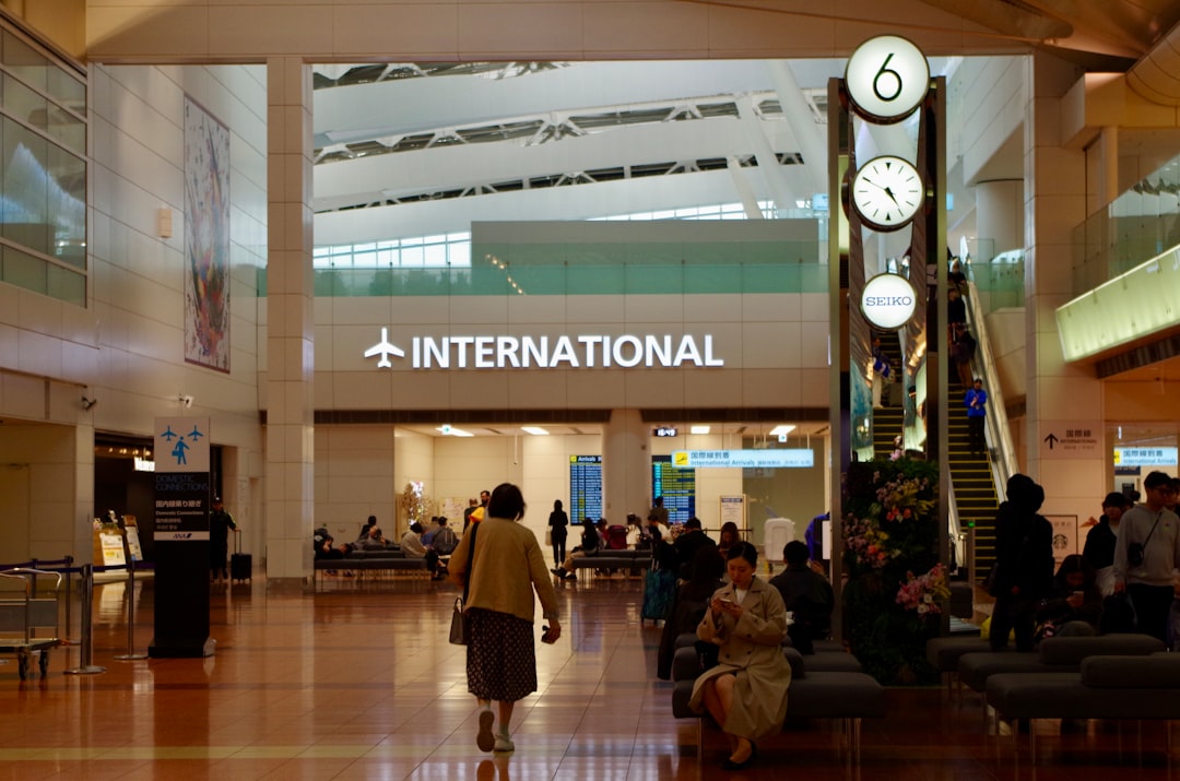
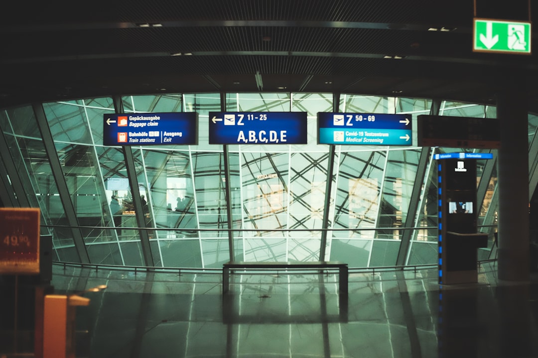
- Why I Almost Missed My Flight Trusting Google Maps — Real 2025 Airport Navigation Guide
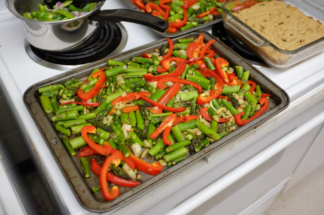
- Why I Almost Gave Up on Meal Prep — And What Finally Made It Stick in 2025
- Why I Almost Gave Up on Egg Rolls — The Real 2025 Guide to Getting Them Crispy Every Time
태그: 전기차구매, 전기차보조금2026, 전기차추천, 아이오닉6, EV6, 전기차vs하이브리드, 전기차총소유비용